100 Discovery Way, Unit 110, Acton, MA 01720 US.
Mon-Fri, 8:00 AM - 5:00 PM (GMT-5)
Connecting Multiple Sensors for Stripper Plate Detection
Your die protection system can be used to monitor the position of a spring-loaded stripper at bottom dead center. If the stripper comes all the way down, the machine is allowed to run; if not, the die protection system will stop the press.
This is useful for detecting pulled slugs, excessive burr, a piece of broken punch lying on top of the strip, or anything else that prevents the stripper from coming all the way down.
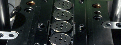
Proximity sensors for stripper detection at BDC
The most common sensor used in this application is the inductive proximity sensor. In order to detect small variations in stripper height, it is usually necessary to use multiple sensors on each stripper - usually a sensor monitoring each corner of the plate.
With four sensors per stripper plate, and sometimes several stripper plates per die, you can very quickly run into capacity limits on your die protection system.
Because of this, many users opt to wire the four sensors monitoring each stripper plate into a single die protection input. There are two ways to do this: the wrong way, and the right way. This article will describe both.
The Wrong Way:
Wire normally open sensors in series (see the diagram below). The sensor input will turn on only when then the
stripper plate comes all the way down and actuates all four sensors.
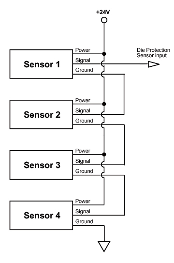
Four N/O sensors wired in series - This method is NOT recommended
There are three potential problems with this approach:
- The wiring is complicated. When wiring electronic sensors in series, the output signal of the first sensor provides the ground (NPN sensors) or the power (PNP sensors) for the next sensor in the series. This forces you to connect some of the sensors' wires to the power supply, some to die protection input, and some from sensor to sensor.
- It won't work for high-speed applications. In series wiring schemes, the first sensor in the series powers up the next sensor, which powers up the one after that, etc. Many sensors have a power-up delay during which time they perform an internal self-test. In a 4-sensor series, this power up delay will occur three times. Depending on the sensors and the press speed, this delay could cause the sensors to miss the very event they're supposed to be monitoring.
- The die protection system might not recognize the sensor actuation. When an NPN sensor actuates, it's output goes from the supply voltage (usually +24 VDC) to a lower voltage - anywhere from .75 volts to 3.5 volts for the "on' condition, depending on the sensor. This residual output voltage in the 'on' condition is called the sensor's "voltage drop". When wired in series, the voltage drops 'stack' and will be added up. In other words, if a single sensor's voltage drop is 3 volts, then the 'on' voltage for two of the same sensors in series will be 6 volts, or 12 volts for a four-sensor series. This is likely not low enough for a die protection system to recognize the input as having actuated.
The Right Way:
Wire normally closed sensors in parallel. The sensor input will turn OFF only when then the
stripper plate comes all the way down and actuates all four sensors.
The wiring is simple: Connect all of the sensors' power wire to the + side of the power supply, connect all of the sensors' ground (return) wires to the negative side of the power supply, and connect all of the sensors' output (signal) wires to a single input on the die protection control.
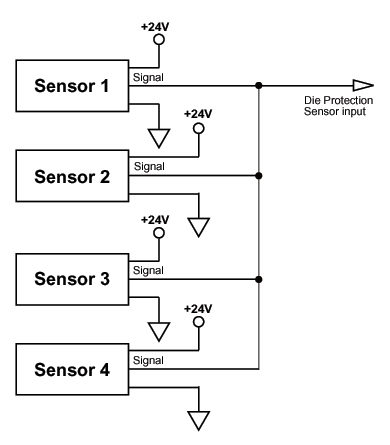
Four N/C sensors wired in parallel - This is the preferred method
The programming for this method requires a slight reversal of logic. Instead of the sensors turning on when the stripper plate reaches the bottom of its travel, the sensors are 'on' all the time, and turn off only when the stripper plate comes all the way down at bottom dead center.
The way to do this is to make the input a "Green Quick Check" sensor type. The ready signal should turn On a few degrees before the stripper plate lifts off the bottom, and turn the ready signal Off a few degrees after the stripper plate arrives at BDC. The sensors are normally closed, so the sensor input will be On (active) when the stripper plate is not at BDC, and will turn off only when all four sensors detect the stripper plate. Since the Green Quick Check sensor type will signal a stop if the sensor input is On (active) any time outside of the ready window, the press will stop if any of the four sensors does not detect the stripper at BDC. The stop type should be set to Top Stop.
© Copyright 2021 Wintriss Controls Group LLC - All Rights Reserved