100 Discovery Way, Unit 110, Acton, MA 01720 US.
Mon-Fri, 8:00 AM - 5:00 PM (GMT-5)
Guidelines for Safety Light Curtains
It's unusual today to visit a press shop and not see safety light curtains in use. In many cases light curtains represent the best solution for protecting the point of operation while having the minimum impact on productivity.
While it may seem as simple as just buying them, hanging them on the press and forgetting about them, there are many maybe not-so-obvious factors to consider when applying light curtains in a stamping operation. If it's done correctly it can be a perfect solution. If it's done wrong, it can have tragic results.
The objective of this light-curtain guideline is to point out the parameters that must be considered by employers and how to assess them. Let's get started!
Table of Contents
A Basic Education on Safety Light Curtains
There are lots of different light curtains.
Go ahead and Google safety light curtains. You'll likely find at least a dozen manufacturers. Light curtains have become a big business due to their versatility. You'll find light curtains on automation machines, robotic cells, coil winders, presses, rollform lines and many other types of machinery. Some of these applications use many light curtains on the same line. As an example, one of the major automotive companies had to retool a pickup-truck-bed line and it incorporated 1200 sets of light curtains.
There are several aspects of selecting the right light curtain. Here are the major ones:
Price - When considering price, make sure to take into account the cost of installation, as some units may be more
difficult to install than others.
Ruggedness - This becomes a major issue in the stamping environment. You'll have to either select one that is designed specifically for the stamping industry or plan to protect a less robust light curtain from die carts, lift trucks and the like.
Safety - Most manufacturers will design systems to meet all of the current standards and regulations as they pertain to control reliability. You can either look for a third-party certification such as CE and CSA, or rely on the manufacturer to provide written assurance that control-reliability standards have been met. One safety-related specification to be on the lookout for is the safety category. This relates to risk assessment. If you'd like to learn more about risk assessment, check out ANSI B11.TR3, which outlines how to determine risk categories for various hazards. Metal stamping and metal-stamping presses almost always fall into a Category 4 hazard. The category is determined by a combination of the potential severity of injury and the frequency of exposure. Category 4 is the highest category, which certainly does not come as a surprise. When selecting a light curtain, check to see that it is Category 4. Manufacturers offer light curtains in Categories 2, 3 and 4. The Wintriss Shadow 9 is a Category 4 light curtain.
Configurations - three box, two box, heads only, interface modules, and cascading.
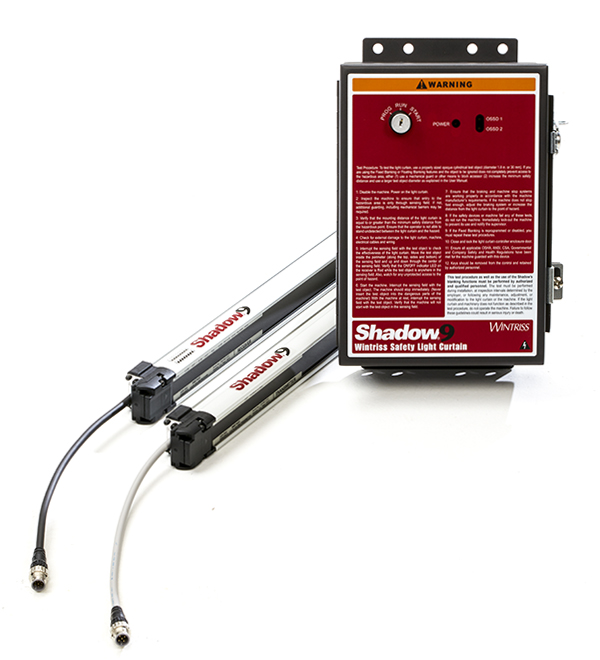
Three-box systems - This configuration includes a transmitter, receiver and control enclosure (see Fig. 1). Some light-curtain systems have transmitters and receivers that are quite small in size. In this arrangement the control box can make it easier to access light curtain features such as blanking. The control box also offers dry contacts, which make it easier to interface to a relay-based press control.
Although they're called "Three-Box" systems, many models (the Shadow 9 being one) allow multiple sets of light curtains to be connected to a single control box.
Two-box system with dry contact outputs - In this configuration, the transmitter and receiver usually will be larger in size (see Fig. 2). The benefit, however, is that there is no third control box to install and they can be connected directly to either relay-based or electronic controls.
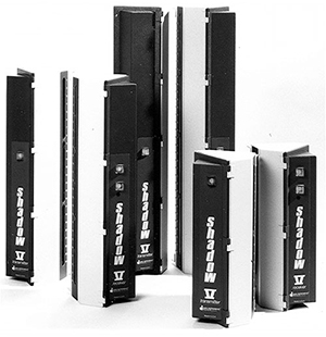
Figure 2 - Two-box Light Curtain Systems
Two-box system with solid-state outputs
These systems also are compact (see Fig. 3).
In many cases these will be less expensive than either of the previous two options. Be aware that these systems usually cannot be directly
interfaced to a relay-based control. They require an interface module to convert the solid-state outputs to dry contacts. Some electronic
clutch-brake controls will have light-curtain inputs specifically designed to accept the solid-state outputs. Check your clutch-brake control
manual or consult the manufacturer.
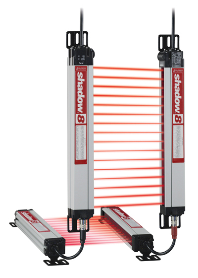
Figure 3 - Two-box system with solid-state outputs
Features - Although they may seem to be very simple devices, there are several features which differentiate light curtain systems intended for stamping presses from general purpose models. Here are some of the important ones:
Blanking - The ability to bypass a portion of the protective field to allow an object to be in the field. The three common types of blanking are fixed, floating and programmable.
- Fixed blanking - This capability can be accomplished by placing a physical object called a blanking window over the face of the light curtain receiver. For a larger blanked area, simply stack multiple blanking windows on top of each other.
- Floating window - This allows you to bypass one or two beams of the light curtain anywhere in the field, which is useful when an object must move within the field. The most common applications include coil stock that must move up and down, and an air or hydraulic clamping hose that moves with the slide.
- Programmable blanking - The newest type of blanking, it's available in many light curtains. With this feature you introduce the object that needs to be in the field and then ask the light curtain to learn the object and bypass the necessary portion of the light-curtain field. Most often when the object is removed, the light curtain will fault out and prevent the press from starting.
Caution: When you blank a portion of the light curtain, the bypassed area extends all the way from the transmitter to the receiver (see Fig. 4). All blanking should be supervisory-controlled and checked frequently. Care must be taken to adjust blanking as jobs change. Make it part of your setup procedures.
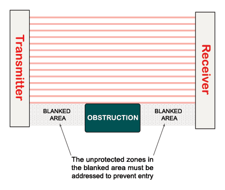
Figure - 4 The Effects of Fixed Blanking
Upstroke Muting - This is the ability to bypass the protective field during a portion of the machine cycle where no hazards exist. Muting can be useful for reaching into the field on the press upstroke, or in some cases for ejecting parts through the light-curtain field.
How upstroke muting is achieved safely:
- Many of the more modern clutch brake controls - Like the WPC 2000 and WPC 1000 - will provide for this capability internally. Special care has been taken within the control to ensure that this is accomplished in a control-reliable manner so that any single component failure will not present a hazard to personnel.
- Control-reliable muting controls also are available. One or two cams or a PLS alone are not safe options.
If you do determine that upstroke muting is required, consult with someone knowledgeable in this area. It's very important that this is done correctly! Upstroke muting should not be confused with the bypassing of a light curtain. Under no circumstances should a light curtain be bypassed in any mode of operation, including inch!
Cascading - This is the ability to string sets of light curtains together, similar to a string of holiday lights (see Fig. 5 below). There are a couple of advantages to this configuration. Wiring becomes easier because you don't have to run wires from each set of heads back to the control. In a three-box system it also can be more cost-effective in that one control box can manage multiple sets of heads.
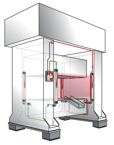
Figure 5 - "Cascading" Light Curtains
Is Your Press a Good Candidate for Light Curtains?
This is an important aspect of safely applying light curtains. A safety device is only as reliable as the entire system, and not all presses are suitable spots for safety light curtains.
For these guidelines, we will only deal with part-revolution-type mechanical-power presses. It is unsafe and illegal to use a light curtain on a full-revolution mechanical-clutch power press. If you still have full-revolution mechanical-clutch presses in your plant, refer to OSHA 1910.217 and ANSI B11.1. There are very specific regulations that deal with the controls and safeguarding on this category of press.
Two types of mechanical power presses fall into this category of partial-revolution machines. They are:
- Air-clutch presses - By far the majority of the press population in the United States falls into this category.
- Direct-drive presses - This is the newest technology in use on a partial-revolution mechanical power press. They are more commonly referred to as servo presses.
What does it take for a press to be good a candidate for light curtains? Simply put, the press system must be control-reliable. Control reliability is the ability of the press to stop in a safe manner if any single component in the systems fails. Although this sounds pretty straightforward, it isn't. Accomplishing control reliability requires a great deal of cross-checking and component monitoring. We can use a light curtain as a good example of this.
Think about how simple its function is:
If you break the protective field, it will send a signal to stop the press.
If you get the opportunity, take a look at the circuitry inside a light curtain. It has hundreds if not thousands of components. They all
exist to accomplish one thing: Control reliability.
You can perform some simple criteria checks on your own. Create a spreadsheet and list the elements below for each press.
Start by checking the dates on your electrical prints (if you have them). Presses built prior to 1971 will not meet
current OSHA and ANSI regulations unless an upgrade already has been performed. Assuming that your press is newer than that,
proceed with the following checks:
-
Dual Safety Valve - The Dual Safety Valve (or DSV) is a critical component to press safety.
It is pretty easy to tell if you have a dual valve or not.
Take a look at the photos below. Figure 6 shows a compliant DSV, Figure 7 shows a single coil, non-compliant valve.
If you're not comfortable making this call then jot down the model number of the valve and call the manufacturer.
It can tell you if it meets the current standards. If you determine that the press has a single solenoid valve,
lock it out until it can be replaced with a DSV. If that single valve should stick, the press will run regardless
of the control system. If you are electrically inclined, the presence of a DSV will be indicated on the press prints.
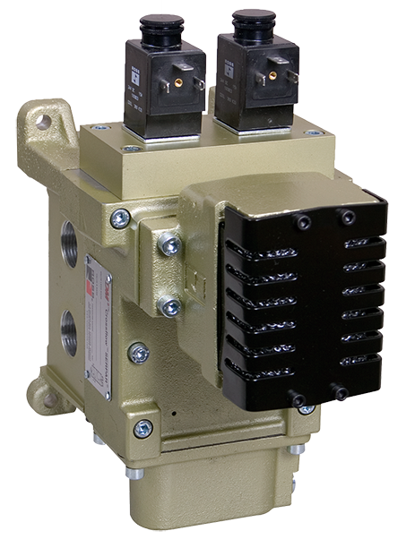
Figure 6 - Dual Safety Valve
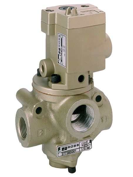
Figure 7 - Non-Compliant Single Coil Valve
- Anti-repeat - Place the mode selector in single stroke. Actuate the palm buttons and hold them down. The press should stop after one cycle. To initiate a subsequent cycle, you should have to release both palm buttons and then actuate them again.
- Anti-tie down - This capability prevents the ability to tie down one palm button and actuate the press with the other button. The latest ANSI standard states that both hands must be on the buttons within ½- sec. of each other. With the mode selector still in single-stroke mode, hold one button down for 1 sec. While still holding it down press the other palm button. The press should not cycle.
- Holding time - In single-stroke mode, you should have to hold the palm buttons down until the ram is close to the bottom of its stroke. At that point, if you remove your hands the press can carry through to the top of the stroke. If you remove your hands midway in the down stroke, the press should stop.
- Supervisory stroke selector switch - Locate the "Inch-Single-Continuous" stroke selector switch and ensure that it is capable of supervisory control, which in most cases means that it is key-actuated.
- Prior action - If your press is equipped with continuous operation, you need to find a "Prior-Act" button required for running the press in this mode. This button can also be called "Continuous Arm" or "Continuous Setup". When the press is placed in continuous mode using the stroke selector, the prior-act button must be depressed before using the palm buttons to start the press in continuous operation.
These tests will give you some sense of where your press stands in terms of compliance and control reliability. This also will give you a tool to compare the findings of a third-party source.
Disclaimer Statement
Most personnel within a metal-stamping facility will not feel comfortable making a determination
regarding control reliability. If you'd like some help, contact Wintriss Controls, or
your local Wintriss representative to do it for you.
Safety Governance
There are several entities which have published rules and regulations that apply to stamping presses:
OSHA - The "Occupational Safety and Health Administration" is a government agency that sets and enforces standards and regulations to ensure safe working environments. The OSHA regulation that governs mechanical power presses is 1910.217. Although it's been around for decades and has had very little updating, many of its basic principles for construction and safeguarding still apply. It does not cover direct-drive servo presses. This regulation is the law of the land.
OSHA state plans - As of January 2019, there were 22 states with their own safety and health programs, which OSHA approves and monitors. If your state has its own plan, please be sure to refer to your state's standards and regulations.
For details about state plans, visit www.osha.gov/dcsp/osp/.
ANSI - The American National Standards Institute (ANSI) is a private non-profit organization that oversees the development of voluntary consensus standards for products, services, processes, systems, and personnel in the United States. ANSI also coordinates U.S. standards with international standards so that American products can be used abroad.
The relevant ANSI standard for mechanical presses is B11.1 and the latest version is from 2009. In order for ANSI standards to remain valid they must be reviewed and updated at least once every 10 years. This latest revision does incorporate guidelines for direct-drive servo presses.
Installation Factors
Safety Distance
Safety distance is a critical factor to consider when installing a safety-light-curtain system on a part-revolution mechanical
power press. It accounts for the time it takes to bring the press to a complete stop after the light- curtain field has been
interrupted. The concept is pretty straightforward but before we can calculate it we must determine the stopping time. Several
components go into finding the total stop time. Let's first look at the two formulas that can be used to calculate the safety distance:
OSHA's formula:
ANSI's formula:
It is the employer's decision as to what safety-distance formula to use. Common practice today is to use the ANSI formula, which employs the more conservative approach.
Stopping-Time Components:- Light Curtain Response Time (Tr) - This is the time that elapses from when the light-curtain field is interrupted to when the light-curtain output device (typically a relay) actually opens. This time usually is quite short, ranging between 20 and 50 msec. It will be indicated either on the light curtain itself or in the technical manual.
- Clutch-Brake Control System Response Time (Tc) - This is the time that elapses from when the light curtain's output is received to when the clutch-brake control actually removes power from the actuating means. In the case of an air-clutch press, the dual safety valve is the actuating means. This time also is quite short. For a microprocessor-based control system, it is likely to be between 15 and 30 msec. For a relay-based control, it could run between 30 and 70 msec. If you are trying to determine this response time for a direct-drive (servo) press, it may be best to get this data from the press manufacturer.
- Brake-Monitor Allowance (Tbm) - This is the time allowed between the actual stopping time of the press and where the brake fault limit is actually set. For example, if a press has a stopping time of 200 msec. and the brake fault is set to 220 msec., then Tbm would be 20 msec. This is an important factor because the brake monitor does not indicate that you are experiencing brake wear until the fault limit is reached, so the safety distance must take this into account.
- Actual Stopping Time of the Press - This will encompass the longest time of all the components. Press stopping time varies depending on factors such as condition of the clutch-brake mechanism, size of the machine, plumbing configuration, counterbalance setting, press PM program, etc. Unless the press is new, it doesn't make sense to get this number from the manufacturer. You'll see a reference below to a 90- deg. stop test. It's been determined that 90-deg. of crank rotation is where the press will have the most momentum and therefore the worst-case stopping time.
There are three ways to determine press-stopping time:
Brake Monitor - The press may be equipped with an electronic brake monitor that has the ability to do a stop-time test at 90 deg. of crank rotation.
Clutch-Brake Control - Many electronic clutch-brake controls such as the Wintriss WPC 1000 and WPC 2000 have a built-in capability to perform a stop-time test at 90 deg. (See Fig. 8).
If the clutch-brake control system does not have a brake monitor or the ability to perform a 90° stop-time test, some advanced automation controllers such as the Wintriss SmartPAC PRO also feature these capabilities. (See Fig. 9).
Stop-Time Measuring Device - You can take these portable devices from press to press to measure the stop time. (See Fig. 10).
The photos below show examples of standalone brake monitors, a clutch-brake control and a portable stop-time device.
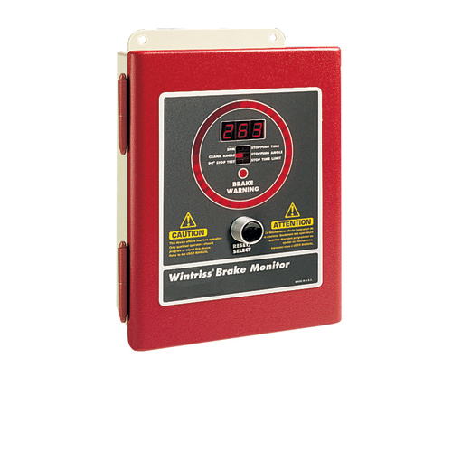
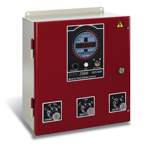
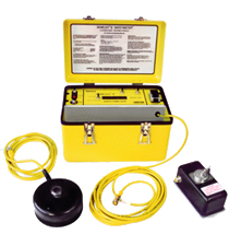
Figure 10 - Portable Stop-Time Measuring Device
Pass-Through Hazard
A pass-through hazard exists when people can place their bodies between the light curtain and the hazard.
This is a common problem that must be addressed. On many larger machines the safety distance will be such that this condition can exist.
Example: A large press can easily can have a stopping time approaching 250 msec. A quick calculation of safety distance using the ANSI formula yields a result of about 2 feet. (This is for illustration purposes only. Some assumptions were made that may not be accurate in all applications.) With a distance of 24 in. between the light-curtain field and the nearest hazard, it would be easy for someone to stand between the light curtain and the hazardous area (See Fig. 11).
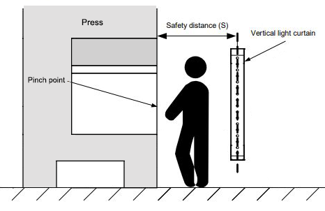
Figure 11 - Pass-Through Hazard Exists Due to Long Safety Distance
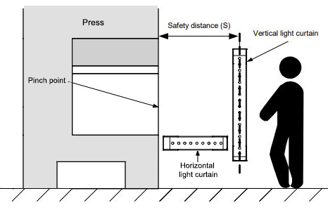
Figure 12 - Additional Horizontal Light Curtain Eliminates Pass-Through Hazard
As the illustration above on the right shows, pass-through protection has been addressed by adding horizontal light-curtain segments. (See Fig. 12).
Over, Under, Around and Through
Under, over, around and through is designed to cover the area that the presence-sensing device does not. If the light curtains are set to the proper size and are long enough, you should minimize this concern, but it cannot be eliminated.
In all cases, you must set the light curtains to the proper distance (see Section IV on Installation Factors/Safety Distance). Once this distance has been established, the size of the light curtains can be addressed. It is impossible to make a blanket statement that covers all scenarios. For example, you may have exceedingly tall employees and need taller lights or have them set higher. Shorter employees may require the lights to be set lower. You also may have situations where some operators run the press while seated versus standing.
Bolster Height
Bolster height can play a role in how long the lights must be as well as if a platform may be in place at times.
If it can be removed for fork-truck access, etc., you must make sure that you are safeguarding the area both when
the platform is in place and when it is out of the way.
Safety Distance
This refers to the distance away from the point of operation. If you have an excessive stopping time and it requires
the lights to be placed at a great distance, you may need excessively long remotes and lights, meaning that the
light-curtain height becomes less of an issue.
Mode of Operation
While all operations have risk involved, we want to minimize that risk. The mode of operation can be an issue here,
since in single-stroke mode, operators usually will have to trigger the press with palm buttons, therefore occupying
their hands during a significant portion of the stroke. In continuous mode, operators may not be using their hands
on every stroke to remove and load parts. However, this freedom allows them to do other things that may be dangerous.
Operators must follow their company's vigorously enforced safe-work procedures.
The guarding of areas not protected by the light curtain must be addressed by additional guarding or lights. In some cases where the lights are at a greater distance, mirrors may be used to set the light-curtain distance with the lights remaining flush to the upright. In other cases, the lights will be at the proper distance and may have remotes to keep you from standing between the light and the hazard. However, someone can reach around the side. In these cases, guarding must be affixed to prevent such action. Guarding must be expansive enough to prevent the operator from reaching over or under.
Using Mirrors with Light Curtains
When using mirrors with light curtains (Fig. 13), several issues must be addressed:
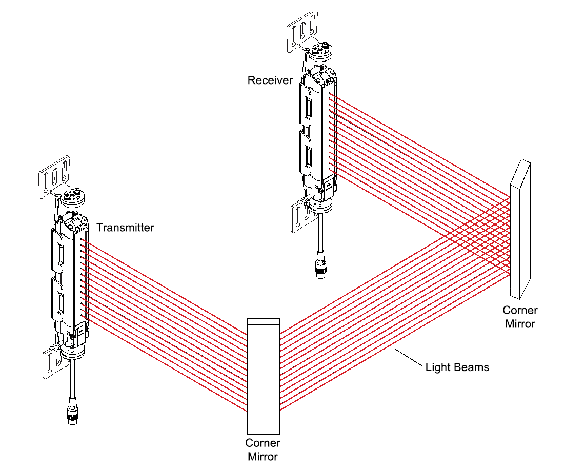
Figure 13 - Three-sided guarding is accomplished using two mirrors
Alignment
When you add mirrors to reflect light curtains around the sides of a machine or to fully encircle the machine,
light-curtain alignment is more critical.
Signal Loss
Mirrors and mirror alignment impact how much signal travels from the transmitter to the receiver.
Less than 100 percent of the signal makes it from the transmitter to the receiver, and the greater
the distance or number of mirrors between the transmitter and receiver, the less the signal transmission.
A good rule of thumb is to deduct 10 percent of the available scanning distance for each mirror used.
Cleaning
Occasional cleaning of the mirrors is required. Some mirrors sold for light-curtain applications are
first-surface mirrors. This means that the reflecting surface is on the outside to minimize signal loss.
This is unlike a bathroom mirror where the reflective surface is behind the plate glass. As a result,
care must be taken not to scratch the surface when cleaning.
Blanking with mirrors
When blanking out an area of the light curtain to allow for an object to be in the field, that blanked-out
area (hole in the field) extends all the way from the transmitter to the receiver.
The use of the mirrors will mean that what you do on the sides impacts the front. For instance, if you have a feed or a chute and you want to use the mirrors, the front safety area is impacted by mounting the lights higher because of feed pass-line height or presence of scrap chutes. Also, a large blanking area for the sides results in a large blanked area on the front.
Light-Curtain Reset Most light-curtain systems provide the ability to reset automatically or manually. This refers to what happens when clearing the light curtain field. In automatic mode, the light curtain will reset itself when the field is cleared, allowing you to start the press operation without any further action. In manual mode, upon clearing, the light curtain will remain in a fault mode until a manual reset button is actuated.
In manual-press operations, automatic mode is commonly used because the light curtains are interrupted frequently and it would be time-consuming to reset them manually each time that this occurs. However, consider using the manual reset mode on automatic press operations or on large presses.
Periodic Testing
Once your installation is complete, you should establish a periodic testing procedure to ensure that the safety system is functioning properly. Current best practices include performing tests at the start of each shift, as part of a job change, or when an operator is changed.This should be a test of the safety system and not just the light curtain. When you perform this test you confirm that the light curtain is sending the signal to stop and that the press is receiving it and stopping accordingly. Most light-curtain manufacturers will provide guidance on some simple tests that can be performed.
What to Do if a Light Curtain Stops Functioning
You'll occasionally experience a light-curtain failure, with the unit either failing over time or becoming the victim of a die cart or fork truck. When this occurs, the press will stop and production will come to a halt. Given the pressure for production, you'll need to find the most expedient way to return the press to an operating condition. There are a few ways to deal with this situation, but first let's talk about what not to do.
Do not bypass the light curtain and leave it in place! There is one thing worse than no safeguarding and that's having a safeguard in place that is not functioning. Personnel will get used to seeing the light curtains in place and believe they are functioning.
What you can do:
Of course the best solution is to have spares in stock so you can quickly swap out a broken unit with a new one.
If you don't have spares and can afford the downtime, remove the light curtain and return it to the manufacturer for repair. Make sure to lock out the machine until the repaired light curtain is reinstalled and tested.
If you can't afford the downtime, remove the broken system, return it for repair and then install some form of OSHA-compliant point-of-operation safeguarding in its place. This will provide the required safeguarding until the repaired system can be reinstalled.
The guidelines above are not intended for any specific application and are not a substitute for each employer's own safety and technical analysis and compliance with the applicable federal or state OSHA standard(s). The Wintriss Controls Group LLC, its officers, employees and consultants assume no liability or responsibility for an employer's failure to comply with applicable federal, state or local laws, or failure to provide adequate safety information and training to employees. This information is not intended and should not be construed as a substitute for legal advice or counsel.
© Copyright 2021 Wintriss Controls Group LLC - All Rights Reserved